3DCS
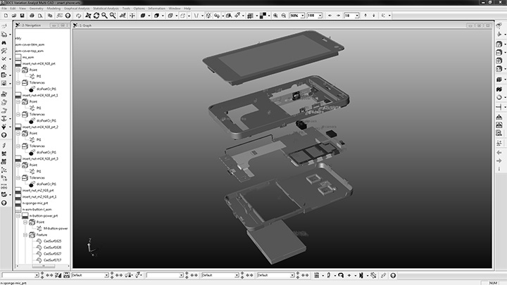
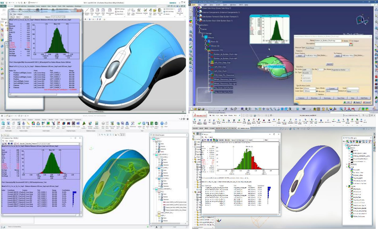
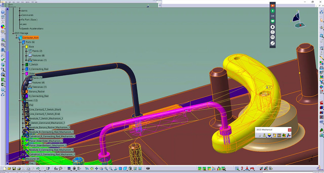
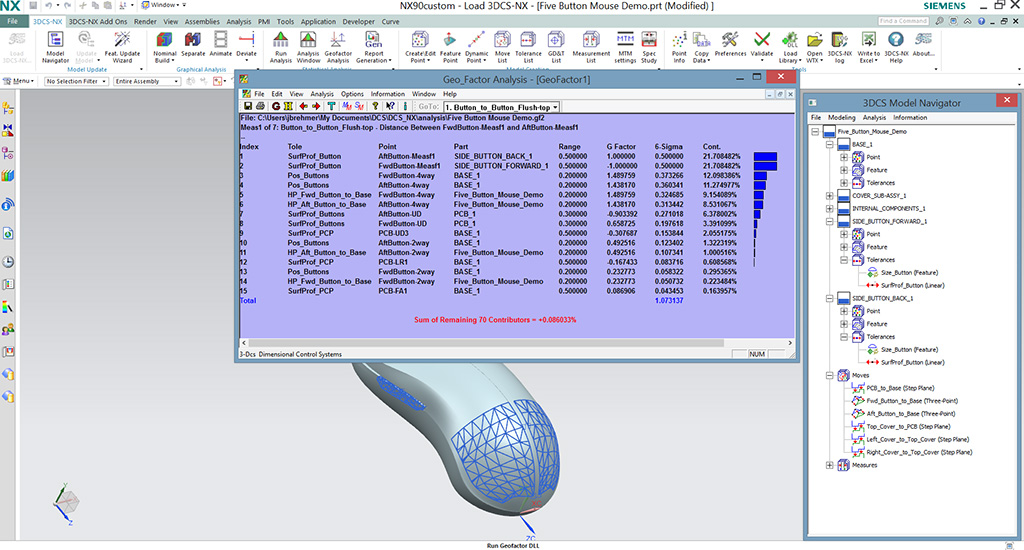
3DCS Variation Analyst is the world's most used tolerance analysis software that is fully integrated into Siemens NX / CATIA V5/ PTC Creo /SOLIDWORKS and CAD Neutral MultiCAD.
It enables designers and engineers to define, test, and modify dimensional product and process requirements in a NX / CATIA V5/ PTC Creo /SOLIDWORKS digital environment before processing. 3DCS Variation Analyst enables manufacturers to quickly evaluate GD&T, assembly tools, and assembly sequences before launching production to fully estimate design, manufacturing, and assembly robustness. Making full use of 3DCS tolerance analysis can reduce the development cost of new products that are quickly brought to market and improve the performance of existing manufactured products.
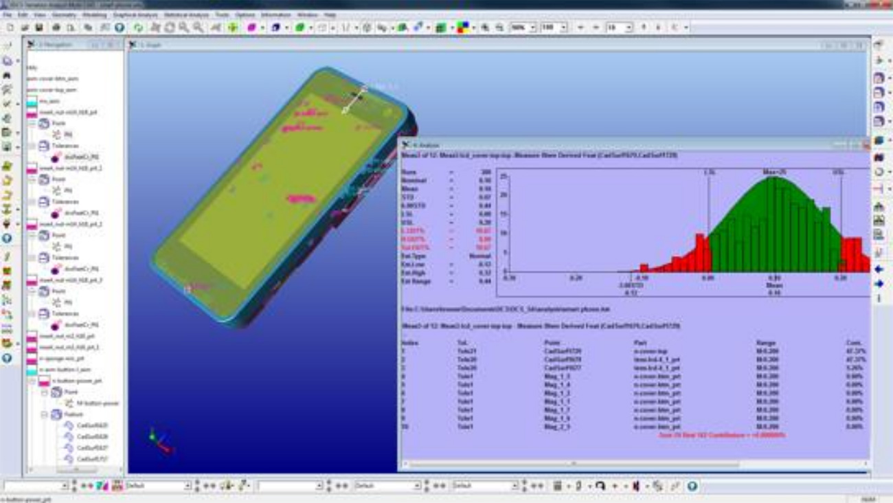
To put it simply: 3DCS assists designers in clearly predicting the Cpk of important product measurement targets during the design phase, analysing and optimizing product portfolio tolerances.

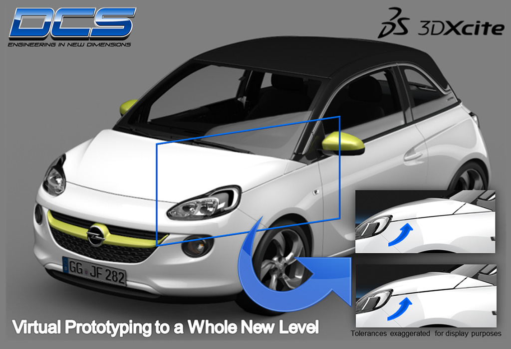
Predict the
assembly variation of manufactured products with virtual prototypes
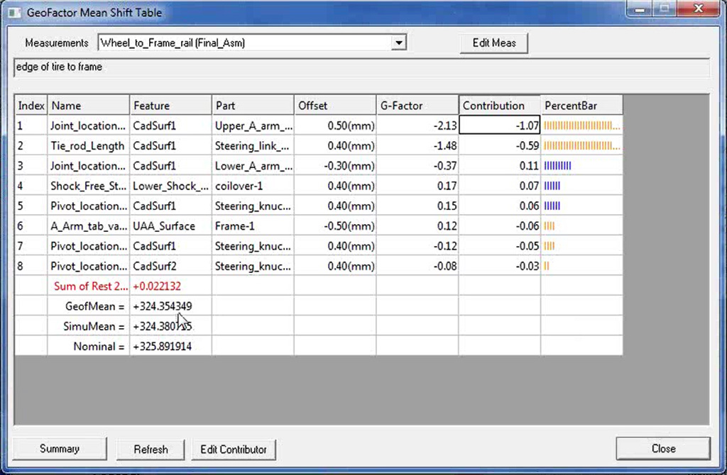
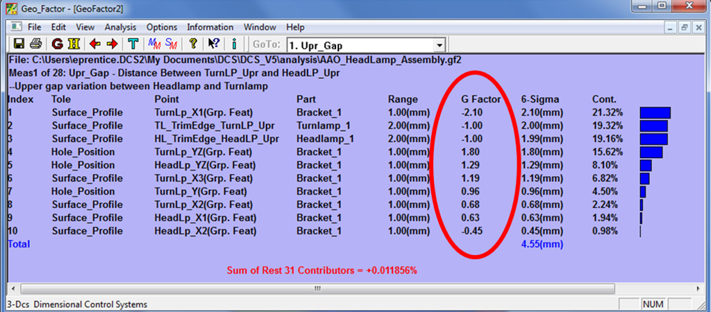
Respond
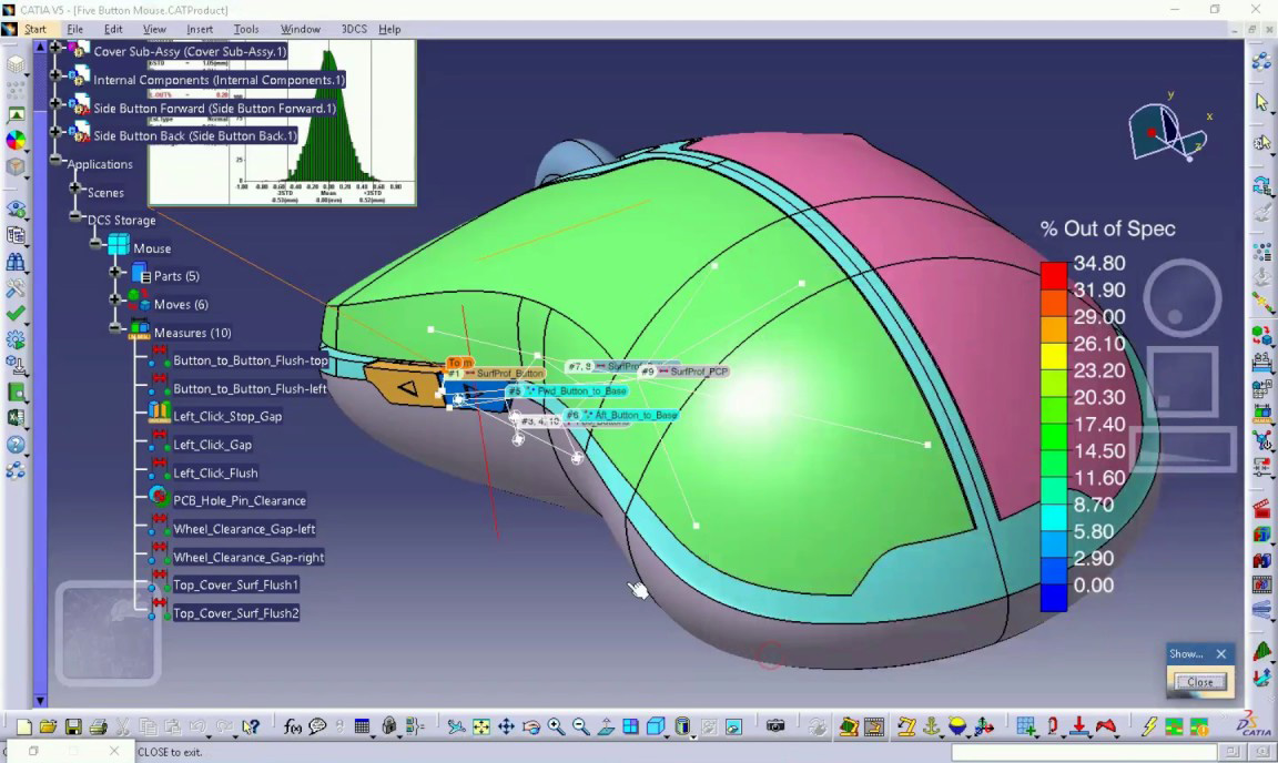
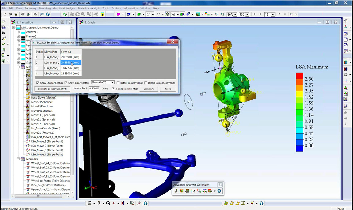
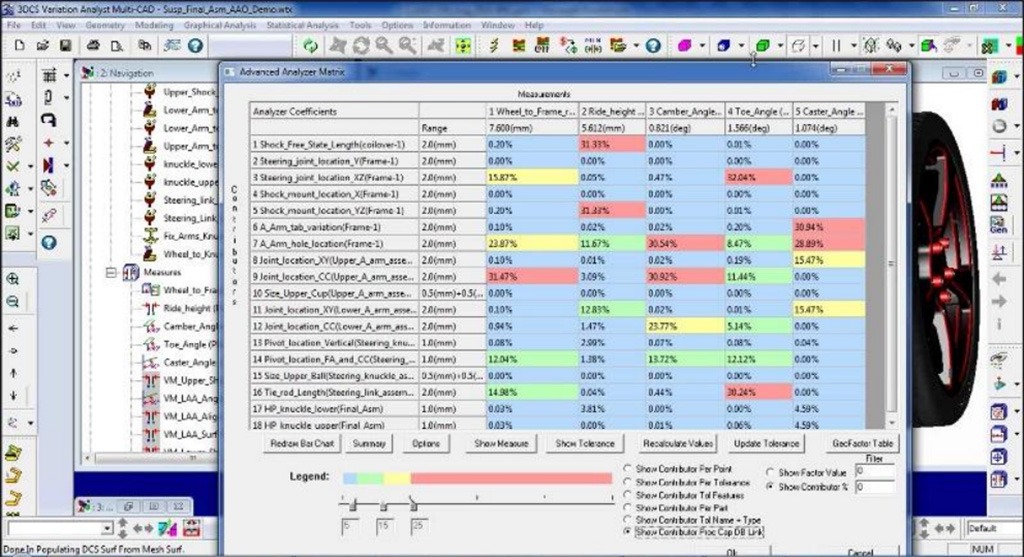
to specific contributors of cumulative variation for optimizing designs
Control
costs and dimensional integrity with proactive variation analysis
Benefits
- Test, optimize and improve your GD&T (Geometric Dimensioning and Tolerancing).
- Determine optimum Gap and Flush conditions based on your manufacturing processes.
- Simulate your manufacturing and assembly processes to determine optimum methods and order.
- Reduce overall variation about compensating for it in design.
- Through robust design and GD&T, reduce the need for scrap and rework.
- Use measurement data from the plant to resolve production issues with the CAD model.