DYNAFORM

A complete die system simulation solution

Dynaform

BSE

FS

D-EVAL

DSA

Optimization Platform

BSE-IN-NX

D-EVAL-IN-NX

logo eta
logo inventium

DynaForm

DYNAFORM is a complete die system simulation solution. It allows organizations to bypass soft tooling, reducing overall tryout time, lowering costs, increasing productivity & providing complete confidence in die system design

DYNAFORM also allows for the evaluation of alternative and unconventional designs and materials for optimal solution.

dynaform

Blank Size Engineering (BSE)

BSE is widely used for estimating blank size, along with blank nesting for maximum material usage, scrap & piece price.

This module offers enhanced forming limit diagram (FLD), thinning, thickening and thickness strain.

Beginning with the 3-D part geometry, BSE can quickly unfold the flanges and flatten the geometry to produce a blank outline for blank size estimation along with piece price and scrap calculation. Product feasibility and cost analysis can be thoroughly evaluated using BSE.

Read more

Part Preparation - Surface Separation

The top and bottom surfaces of a solid-model part can be separated, showing the material from both inside and outside and the mean(middle) surface can be generated automatically. There are also multiple functions to repair surface defects.

Blank Development

BSE includes an industry proven solver (MSTEP) for the accurate prediction of flat blank profiles from 3-D part geometry. Designed for cost estimators, blank predictions consider both linear bends and the material stretch that occurs during the forming process to produce the most accurate blank possible.

Nesting

The BSE module provides for 1-up, 2-up and multiple blank nesting. The material usage and fall off is calculated along with piece price. Minimum required blanking tonnage is estimated. Nesting optimization can be performed to calculate the best material utilization.

Cost Estimation Report

Automatically generate reports for cost estimation and quotation of the part material. Report output includes detailed descriptions of overall blank size, nesting configuration, pitch, coil width, material utilization, number of coils required to meet annual volume and total piece price for materials.

Feasibility Study using MSTEP

MSTEP is a one-step code which can be used for quick formability of a part. Binder, addendum and drawbeads can be simulated with pressure pads, binder and drawbead force.

Trimline Development with MSTEP

MSTEP will quickly and easily develop the trimline throughout multiple stations.

blank size engineering
formability simulation-1
formability simulation-2

Formability Simulation (FS)

This module facilitates the rapid development & validation of single-station & progressive die designs.

FS help to uncovers hidden problem areas & enables designers to optimize designs based on accurate forming results.

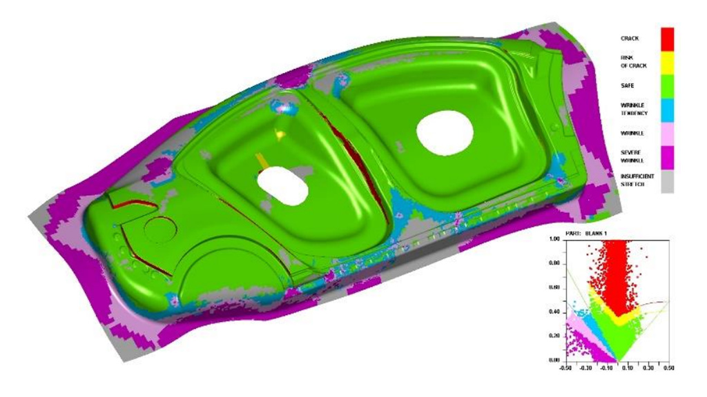
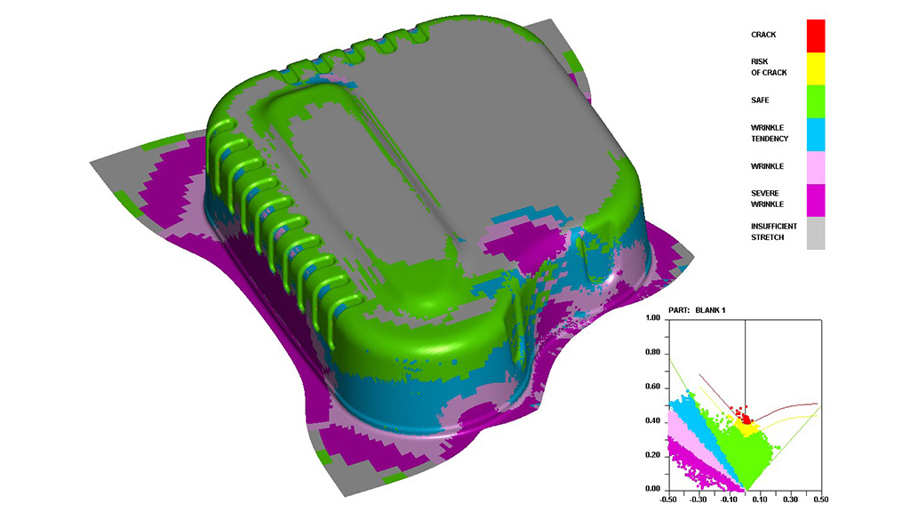
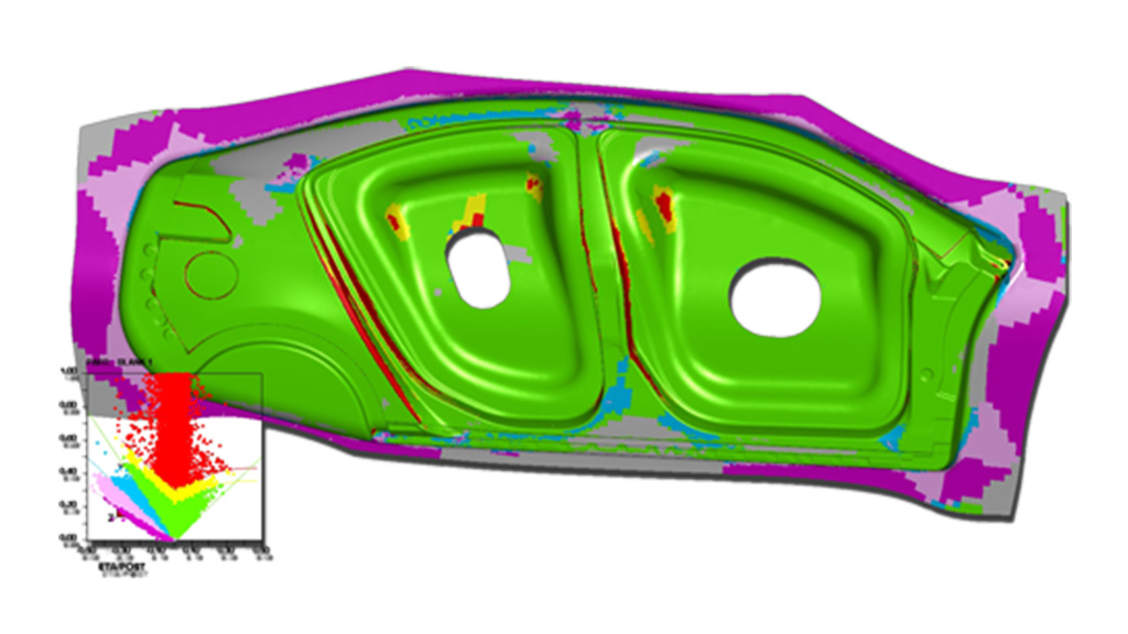
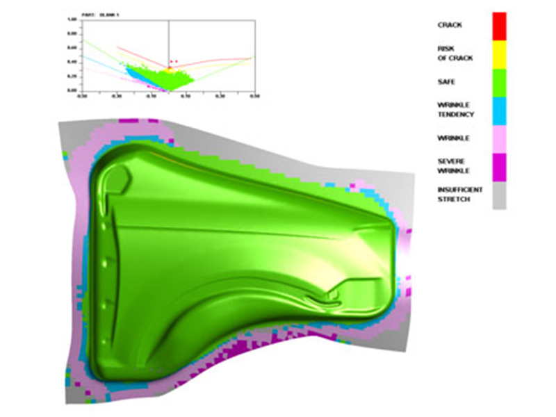
The Formability Simulation module uses LS-DYNA for accurate physics modeling, efficient calculation and in-depth simulation of the formability based on the die design. The FLD (forming limit diagram), thinning map, wrinkling, material draw-in, circular grid, light strip and skid mark results identify weaknesses of the die design.

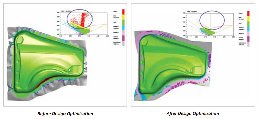
New! Optimization Capability

With DYNAFORM Version 5.9, the engineer can more effectively design drawbeads that restrict the blank from wrinkling & splitting during the forming process, significantly reducing the time required to achieve a formable part.

It streamlines the challenging and time consuming process of laying out drawbeads for large and complicated parts and guides the engineer to efficiently achieve optimum configurations for drawbead forces.

This feature streamlines die design, improves product performance and reduces manufacturing time by using simulation iterations as a search engine for the best possible design solution. As a result, higher performing, higher quality products can be developed, while greater manufacturing efficiency is achieved.

Read more

MSTEP & QuickSetup

In this module, a one-step solution using MSTEP is included to perform a quick evaluation of part formability. FS includes a QuickSetup for standard single-stage draw die and springback simulations.

Autosetup and Multiple-Stage Simulations

AutoSetup is available for complicated multiple-stage forming setups for all formability applications of various die systems. The AutoSetup interface visually guides the user through the setup process. All travel curves are automatically generated and multiple-stations can be setup seamlessly.

Hydroforming Capabilities

FS can support tube bending, tube hydroforming and sheet hydroforming.

Springback & Springback Compensation Process (SCP)

Using the DYNAFORM SCP, the user can determine and simulate the amount of springback compensation; simply define the selected tool to be compensated in SCP.

Special Forming Processes

FS can support stretch forming, thermal forming, roll forming and super plastic forming for specialized manufacturing processes.

Material Library

To maintain accuracy, the bundled material library contains a large selection of standard material types and users can also customize the library to meet specific needs such as:

  • Gravity Load
  • Draw Die
  • Crash Form
  • Inverted Draw (Single Action)
  • Toggle Draw (Double Action)
  • Trimming
  • Flanging
  • Re-strike
  • Springback and Springback Compensation
  • Tube Bending & Hydroforming

Die Evaluation (D-Eval)

A CAE solution, D-Eval is tailored to support engineers in the early stages of the product design cycle.

It allows engineers to take manufacturability into consideration early in the design process, ahead of the tooling stage.

D-Eval includes the INCSolver, which allows engineers to generate reliable formability results in a reasonable response time.

Since most tooling designs are done in a CAD environment, DYNAFORM’s D-Eval Module is specially created to support and analyse CAD based tooling and engineering designs. D-Eval provides useful CAE tools to enable engineers to quickly modify die design. These include:

Read more

D-Eval Provides CAE Tools for “What If” Studies:
  • Tipping Adjustments
  • Binder Generation & Modifications
  • Morphing
  • Drawbead Layout
  • Line Bead & Geometry Bead Conversion
  • Addendum Modifications
  • Die Design Modifications
  • CAM Trim Evaluation
  • Trim Line Checks
INCSolver

The D-Eval Module Includes the INCSolver, which is a nonlinear transient dynamic finite element program. It was developed solely for the purpose of simulating sheet metal forming processes.

Using Shared Memory Processing (SMP), users can take advantage of the multiple-CPUs, Multiple-Cores and Multiple-Threads of the latest Windows computing platform. This allows for quick and reliable results. For most cases with a 4-core CPU, results can be generated in just minutes.

The INC Solver works well with non-connected mesh generated from non-conforming CAD surfaces. This solution is most suitable for CAD engineers and directly interfaces with all major CAD systems. In addition, the INCSolver’s features and functions are excellent for early stage tooling evaluation and are very simple to learn and use.

Streamlined interface for common die face engineering applications including:

  • Gravity Load & Binder Wrap Simulation
  • Crush Forming Simulation
  • Single Action Simulation
  • Double Action Simulation
  • Tailor-welded Blank
  • Trimming & Lancing Function
die evaluation
die system analysis

Die System Analysis (DSA)

DSA efficiently predicts many stamping related concerns within the die production line. It is used to analyse scrap shedding/removal, die structural integrity & sheet metal transferring/handling.

The Finite Element Analysis approach to die system design is an efficient way to predict and resolve many stamping related concerns within the die production line.

Die System Analysis (DSA) simulations streamline die system design through the analysis of scrap shedding/removal, structural integrity and sheet metal transferring/handling.DSA's process guidance approach allows engineers to use simple graphic interfaces to execute complicated preparation and simulation processes.

Read more

Scrap Shedding & Removal (SHR)

The number one cause of stamping line shutdown is the failure of scrap to exit the workstation. This problem can be predicted and corrected in the trim die design stage to avoid troubleshooting in the stamping plant. SHR streamlines model generation for scrap, trim dies, chutes and trim steel. Trimming operations and shedding simulations can be easily setup in the scrap shedding graphic interface.

Die Structural Integrity (DSI)

DSI simulates operational loads to analyze the design integrity of the die. DSI can generate FEA models of the die structure, define operational/stamping loads and evaluate the die structure strength and durability by using implicit and explicit solutions.

Sheet Metal Transferring & Handling (SMTH)

SMTH simulates the transfer of metal as it progresses through the manufacturing process. It simulates the transfer of the work-piece to the initial die station, movement between stations, pick-up of the finished part and placement on the shipping rack. Part deformation generated in the simulation is used to predict interference between the work-piece and tools. The stress/strain results can be used to prevent damage during transportation, as well as loading and unloading operations.

Optimization Platform

This module helps users to go beyond identifying problem areas, by incorporating design optimization to improve performance and quality - reducing wrinkling, thinning and tearing.

Optimization of sheet metal forming is now possible using DYNAFORM™. The most accurate die analysis tool available, DYNAFORM™ is now enhanced with the HEEDS* optimization search engine, SHERPA.

Read more

DYNAFORM Enhanced with Optimization - Develop & design a formable part more quickly than ever.

For many years, DYNAFORM has been used by tooling engineers as a virtual tryout for metal stamping. Engineers can go beyond identifying problem areas by incorporating design optimization to improve performance and quality - reducing wrinkling, thinning and tearing. In the simulations shown, cracking is greatly reduced (red areas).

The incorporation of optimization streamlines die design, improves product performance and reduces manufacturing time and cost by first specifying constraints and then allowing simulation iterations to search for the best possible solution. As a result, higher performing, higher quality products can be can be developed, while greater manufacturing efficiency is achieved.

Using design optimization, a firm can reduce costs by identifying the optimal variables for sheet metal stamping. Production constraints can be entered as guidelines and SHERPA finds the ideal values for the specified variables. Namely, OP uses this process to optimize drawbead rates. The system identifies the optimal values and updates the database automatically.

optimization platform
BSE-in-NX

BSE-in-NX

BSE is a complete solution for accurately estimating blank size along with blank nesting for maximum material utilization, minimum scrap and piece costs—all within the NX environment.

The solution can quickly produce a blank outline for blank size estimation along with piece price and scrap calculation.

Designed for cost estimators, blank predictions consider both linear bends and the material stretch that occurs during the forming process to produce the most accurate blank possible. The solution also provides for ‘1-up’, ‘2-up’, ‘2-pair’, ‘mirrored’ and ‘multiple blank’ nesting configurations.

BSE-in-NX can also automatically generate reports, which include detailed descriptions of overall blank size, nesting configuration, pitch, coil width, material utilization, number of coils required to meet annual volume and total piece price for materials.

Read more

Part Preparation
  • Separates top & bottom surfaces of solid-model parts
  • Automatically generates middle surfaces
  • Fixes & fills surface gaps & holes
  • Automatically meshes
  • Tips double-attached parts
  • Fills holes & gaps between double-attached parts & creates sidestep
Nesting
  • Allows nesting with imported, created or MSTEP generated outline
  • Supports outline development, editing & deletion
  • Optimal 1-up, 2-up, 2-pair, mirror & multiple blank nesting
  • Fitted geometry shape nesting: rectangle, parallel, trapezoid, isosceles trapezoid & arc
  • Supports nesting with fixed angle, pitch or width
  • Supports nesting with the range of angle, pitch &width
  • Allows nesting in plate to align the outlines in plate position
  • Calculates material utilization, fall-off & piece cost
  • Calculates 3D trim line of each outline & outputs IGES
  • Outputs 3D trim line in the original position & tipping position for double-attached parts
Forming Analysis
  • Generates a forming limit diagram (FLD)
  • Predicts thickness, thinning, thickening & strain
Report Generation
  • Cost estimation reports (maximum material utilization & product piece cost)
  • Formability reports (thickness, thinning & FLD)
  • Supports different output units for nesting reports
  • Offers a combined report for tailor welded blanks

D-Eval-in-NX

Analyse CAD Based Die Designs in NX environment. DYNAFORM’s D-Eval-in-NX module is specially created to support and analyse CAD based tooling and engineering designs within the native NX environment.

This solution offers to support engineers in the early stages of the product design cycle. It allows engineers to take manufacturability into consideration early in the design process, ahead of the tooling stage.

Read more

Analyze CAD Based Die Designs in NX

Since most tooling designs are done in a CAD environment, DYNAFORM’s D-Eval-in-NX Module was specially created to support and analyze CAD based tooling and engineering designs within the native NX environment.

A CAE solution, D-Eval-in-NX is tailored to support engineers in the early stages of the product design cycle. It allows engineers to take manufacturability into consideration early in the design process, ahead of the tooling stage.

D-Eval-in-NX includes the INCSolver, which allows engineers to generate reliable formability results efficiently. The INCSolver is a nonlinear transient dynamic finite element program using an explicit method to solve equations of motion, commonly called “incremental code”. It was developed solely for the purpose of simulating sheet metal forming processes.

Using Shared Memory Processing (SMP), users can take advantage of the multiple-CPUs, Multiple-Cores and Multiple-Threads of the latest Windows computing platform. This allows for quick and reliable results. For most cases with a 4-core CPU, results can be generated in just minutes. The INCSolver works well with non-connected mesh generated from non-conforming CAD surfaces.

This solution is most suitable for CAD engineers and is directly operated in the native NX environment. In addition, the INCSolver’s features and functions are excellent for early stage tooling evaluation are very simple to learn and use.

D-Eval-in-NX

Turn your idea into reality

Engineered Solution. Our Passion.

If you want to learn more about DFETECH, please send us a message or give us a call. We would love to hear from you